Cable Fill Rate Calculations
The available space on a raceway system is generally calculated depending on the inside dimensions of a system. On that score there is a definition of material thickness or inside dimensions in the raceway catalog configuration. Depending on the variant of laying method, there can be parameters which can be modified in the configuration.
Depending on the different cable laying methods, the cross section of a cable is calculated round or square as shown in the following description of the single methods.

Multi Layer
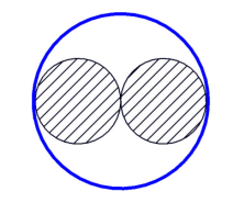
A raceway section, using the Multi Layer method can absorb cables in multiple layers, like shown in the following image. The cross section of a cable is calculated square. The Order in which cables are layered depends on a cable's priority. Cables with higher priority are laid first followed by cables with lower priority (e.g. smaller cables). For this laying method, there are no parameters available.
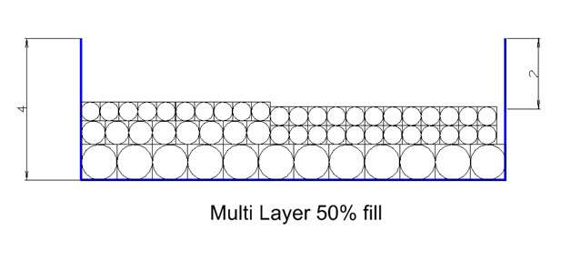
The fill rate is calculated as the relation between the cross section of the raceway section and the sum of cable cross sections. In the image above it's 50% for example.
Single Layer
The Single Layer method allows only one layer of cables on a raceway section. Generally there is one parameter available to define a fix space between the single cables, but it's default value is 0.
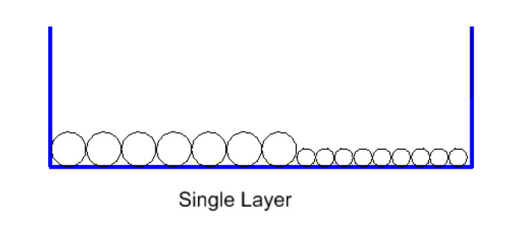
Fill rate is calculated as the relation between the internal width of the raceway section, the sum of cable diameters and any optional defined spaces, when parameter 1 ≠ 0.
Single Layer spacing equals largest cable diameter
The Single Layer spacing equals largest cable diameter method allows only one layer of cables on a raceway section. The space between the cables is fixed definition using the diameter of the largest absorbed cable on a raceway section as the measurement. For this laying method, there are no parameters available.

Fill rate is calculated as the relation between the internal width of the raceway section and the sum of cable diameters and spaces.
Triangular
The Triangular cable laying method is typically used for 3 phase large power cables. The Triangular cable laying method can be used only in conjunction with circuit numbers definition imported from a cable list ( or manually assigned in cable manager). Three Cables with same circuit number will be grouped together into a triangular configuration.
There are two parameters definable in the configuration.
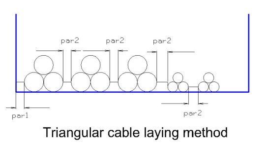
Presetting of parameters in metric dataset:

Fill rate is calculated as the relation between the internal width of the raceway section and the sum of cable diameters and spaces of parameters.
The system also checks, if the height of the largest triangular package fits into the internal height of the raceway section.
Single Cable
The Single Cable method only considers the number of cables on a raceway section, regardless the dimensions of the cable or raceway system. There is a parameter definable in the configuration to change the maximum permitted number of cables. The default value is 1.
The fill rate calculation is uses the relation between maximum permitted cables and currently routed cables. If the max. value is 2, for example and the number of routed cables is 1, the fill rate is calculated to 50%, regardless to the dimensions.
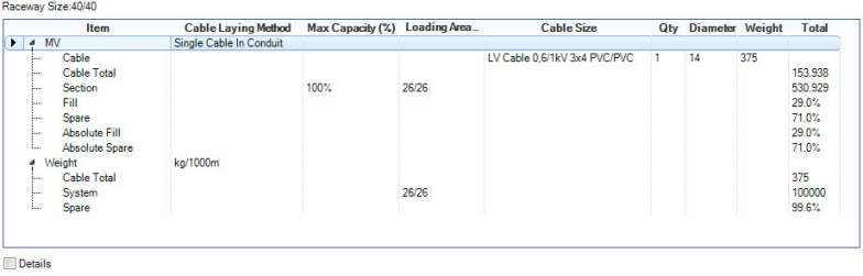
Single Cable in conduit
The Single Cable in conduit method is particularly defined for conduits. The default number of maximum permitted cables is set to 1. The automatic routing function will consider that max. number and will not pass over, regardless of the dimensions.
The fill rate calculation does consider the dimensions. The cross section of the conduit is calculated as a circular area in regards to the internal diameter and also the cross section of the cable is calculated as a circular area.
Example:
Multiple Cable in conduit
The Multiple Cable in conduit method is particularly defined for conduits.
The fill rate calculation considers the cross section of the conduit, calculated as a circular area in regards to the internal diameter as well as the cross section of the cables, calculated as a circular area.
The fill rate is calculated as the relation between the cross section of the conduit section and the sum of cable cross sections.
The automatic routing function also considers, that the number of cables fits geometric into the conduit.
Max Layer (2 layers)
The Max Layer (2 layers) method is similar to the Single Layer method, but there is a parameter available in the configuration ”Parameter 1" with a default value of 2. So the raceway section can absorb 2 layers of cables.
Fill rate is calculated as the relation between the internal width of the raceway section, multiplied with the number of layers (2) and the sum of cable diameters.
Max Layer (3 layers)
The Max Layer (2 layers) method is similar to the Single Layer method, but there is a parameter available in the configuration ”Parameter 1" with a default value of 2. So the raceway section can absorb 2 layers of cables.
Fill rate is calculated as the relation between the internal width of the raceway section, multiplied with the number of layers (3) and the sum of cable diameters.